Urvashi Sengal
Mini-Circuits
Kit Cox
Mini-Circuits Japan
Directional couplers are an important type of signal processing device. Their basic function is to sample RF signals at a predetermined degree of coupling, with high isolation between the signal ports and the sampled ports — which supports analysis, measurement and processing for many applications. Since they are passive devices, they can also be used in reverse: a signal fed into the coupled port will be injected onto the mainline, with the coupling factor and directivity determining how the injected signal is distributed. Directional couplers are available in several configurations, each described below.
Definitions
Ideally, a coupler would be lossless, matched and reciprocal. The basic properties of three- and four-port networks are isolation, coupling and directivity, the values of which are used to characterize the couplers. An ideal coupler has infinite directivity and isolation, along with a coupling factor selected for the intended application.
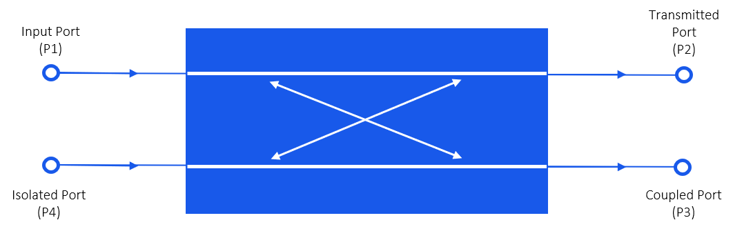
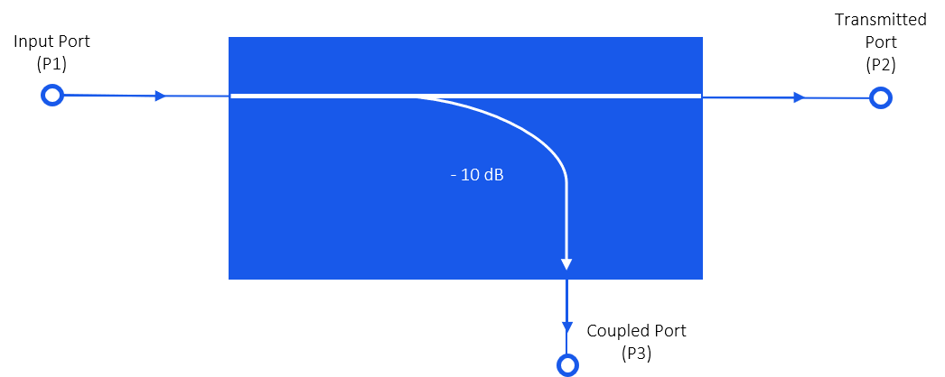
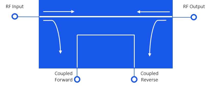
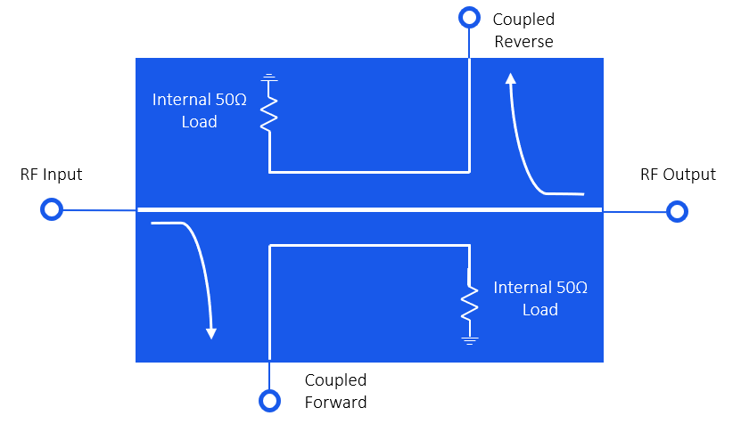
The functional diagram in Figure 1 illustrates the operation of a directional coupler, followed by a description of the related performance parameters. The top diagram is a 4-port coupler, which includes both coupled (forward) and isolated (reverse, or reflected) ports. The lower diagram is a 3-port structure, which eliminates the isolated port. This is used in applications that only need a single forward coupled output. The 3-port coupler can be connected in the reverse direction, where the port that was formerly coupled becomes the isolated port:
Performance Characteristics
- Coupling Factor: The fraction of the input power (at P1) that is delivered to the coupled port, P3
- Directivity: A measure of the coupler’s ability to separate waves propagating in forward and reverse directions, as observed at the coupled (P3) and isolated (P4) ports
- Isolation: Indicates the ratio of input power (P1) to the power delivered to the isolated port (P4).
- Insertion Loss: Indicates the ratio of input power (P1) to the power delivered to the through port (P2). This includes power diverted to the coupled and isolated ports, as well as dissipative losses within the coupler.
The value of the above characteristics are expressed mathematically in dB as:
Coupling\,Factor = C = 10 \log \left( \frac{P_1}{P_3} \right)Directivity = D = 10 \log \left( \frac{P_3}{P_4} \right)
Isolation= I = 10 \log \left( \frac{P_1}{P_4} \right)Insertion\, Loss = L = 10 \log \left( \frac{P_1}{P_2} \right)Types of Couplers
Directional Couplers
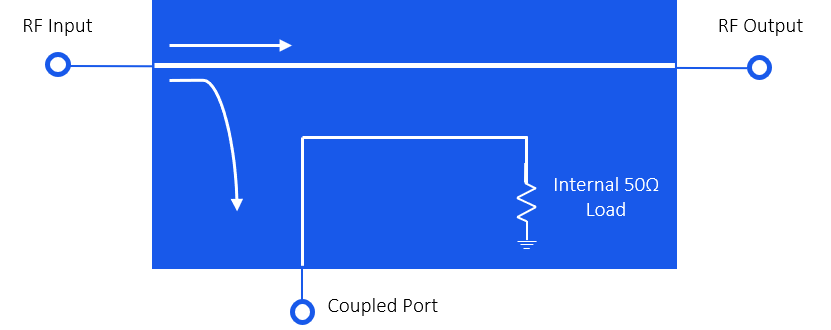
This type of coupler has three accessible ports, as shown in Figure 2, where the fourth port is internally terminated to provide maximum directivity. Although it can be connected in reverse, this type of coupler does not perform identically when reversed. Since one of the coupled ports is internally terminated, only one coupled signal is available.
In the forward direction (as shown in Figure 2), the coupled port samples the forward wave, reduced by the coupling factor. This may be used to deliver a portion of the output signal to feedback circuitry or for output power monitoring.
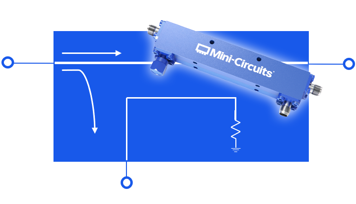
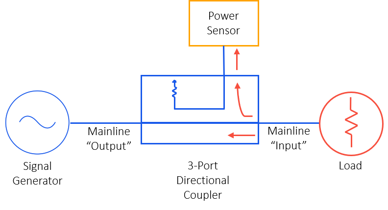
One common use of a directional coupler is to sample reflected signals (or indirectly, VSWR). To achieve this, we can connect the coupler in reverse — with its input port facing the load instead of the source (see Figure 8 below). The forward signal from the source passes through the mainline without coupling to the coupled port (the coupled energy is instead dissipated in the internal termination), while any reflected wave from the load enters the coupler’s input port in the coupler’s forward direction. The coupled port then provides a sample of this reflected wave, reduced by the coupling factor. This configuration may be used for reverse power measurement or VSWR monitoring.
Advantages
- Coupler performance is optimized for only one direction
- High directivity and isolation
- Since the directivity of a coupler is strongly affected by the impedance match at the isolated port, furnishing that termination internally ensures consistently high performance.
Disadvantages
- Coupling is only available in one direction
- The coupled port power rating is less than the input port because the power applied to the coupled port is almost entirely dissipated in the internal termination.
Example
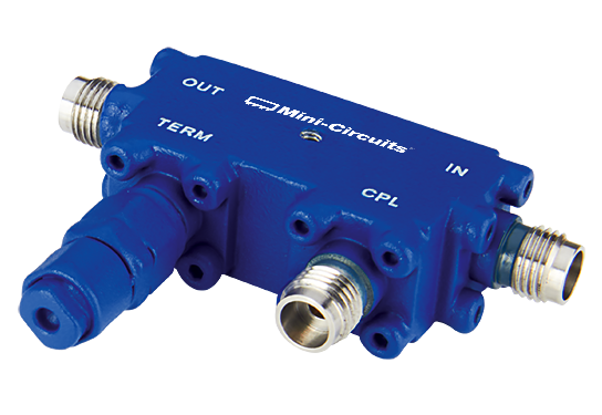
Mini-Circuits ZCDC20-E18653+ is a coaxial directional coupler with 20 dB nominal coupling across the 18 to 65 GHz frequency range. This model provides RF input power handling up to 12W and passes DC current up to 0.48A

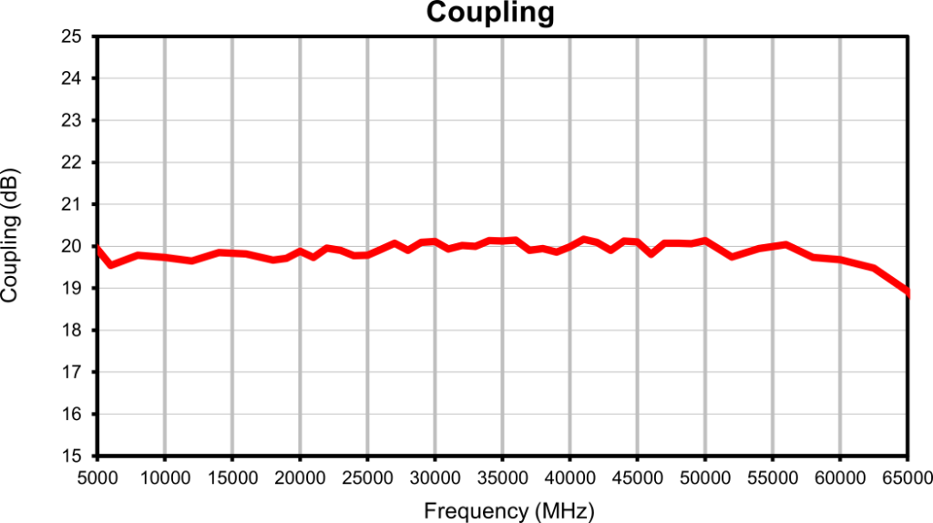
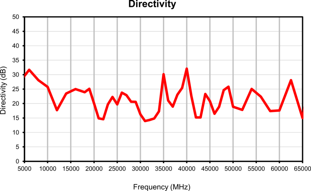
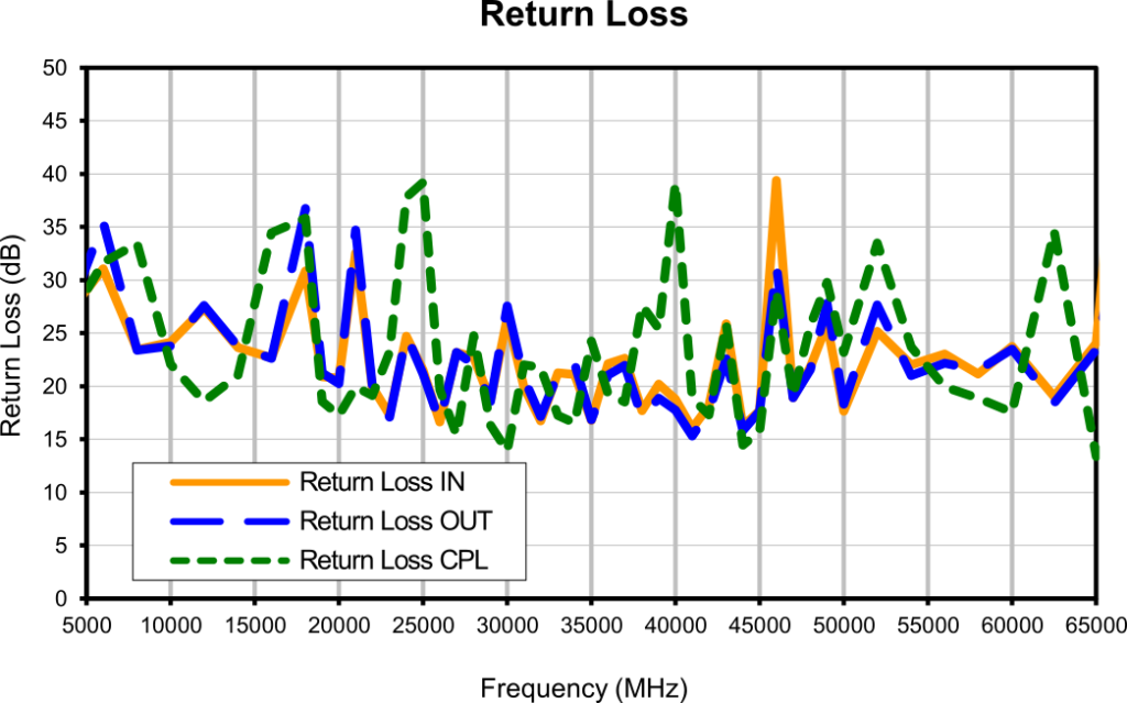
Figure 3: Performance curves for Mini-Circuits’ ZCDC20-E18653+ directional coupler
Bi-directional couplers
This coupler type has four ports, all accessible for the customer to use. It has a symmetric design, allowing forward and reverse signals to be sampled simultaneously. It is the user’s responsibility to properly match or terminate both coupled ports.
Advantages
- Symmetric design
- Input and output ports are interchangeable
- There are two transmission lines, coupled line works the same as the mainline
- Forward and reverse coupling available
Disadvantages
- Design is critical to maintaining good performance in both directions
- The directivity of the coupler depends on how well the isolated port is terminated
Example
Mini-Circuits’ ZGBDC35-93HP+ is a coaxial bi-directional coupler with 35 dB nominal coupling across the 900 to 9000 MHz frequency range. This model provides 250W RF input power handling and passes DC current up to 3A.
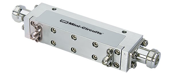
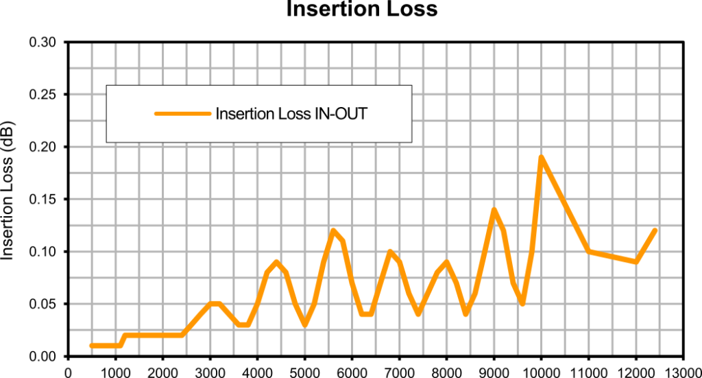
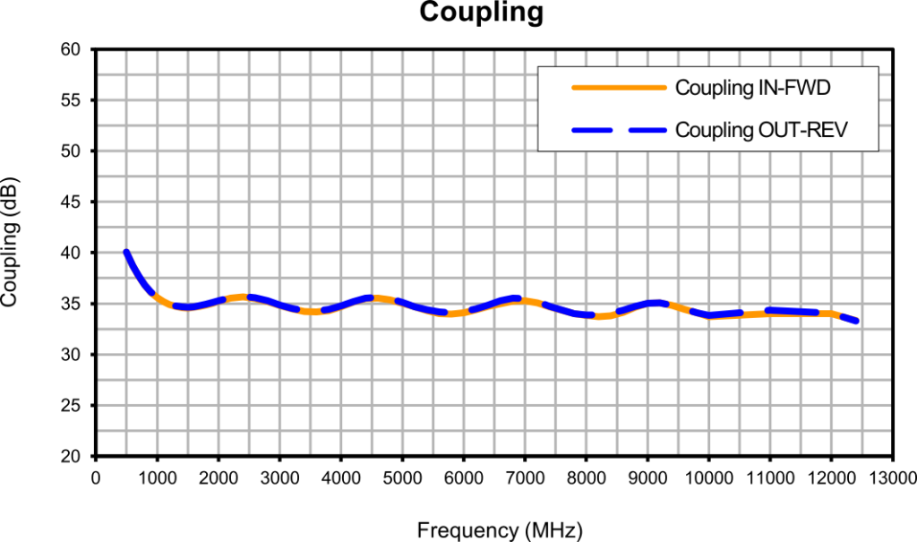
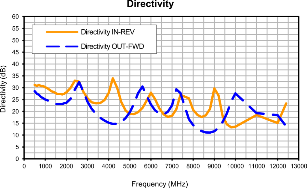
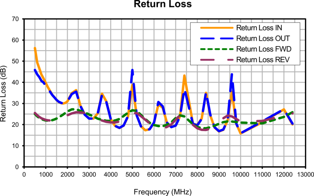
Figure 5: Performance curves for Mini-Circuits ZGBDC35-93HP+ bi-directional coupler
Dual Directional Couplers
This third type of coupler is a combination of two 3-port couplers placed back-to-back. This configuration provides bi-directional coupler action as well as independent forward and reverse coupled ports. The primary advantage is that because each coupled port belongs to a separate internal coupler with its own termination, a mismatch on one coupled port will not affect the other.
Advantages
- Performance can be optimized for both forward and reverse paths
- Higher directivity and isolation can be achieved
- Provides forward and reverse coupling
- Directivity of one path is not affected by mismatch present on the other path
- Can be used to simultaneously monitor both the forward and reverse power of a system
Disadvantages
- Larger size compared to directional and bi-directional couplers
- No through path available between forward and reverse coupled ports
- Higher insertion loss than single directional and bi-directional couplers
Example
Mini-Circuits DDCH-50-13+ is a stripline-based surface-mount dual-directional coupler with a 50 dB nominal coupling ratio across the 20 to 1000 MHz frequency range. This model provides up to 120W RF input power handling and DC current passing up to 4A.
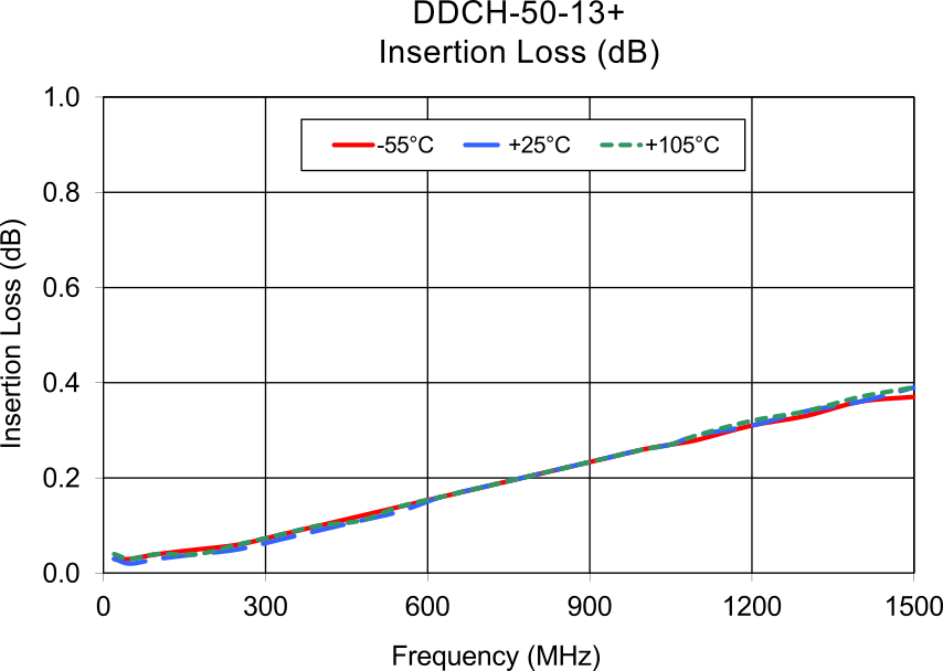
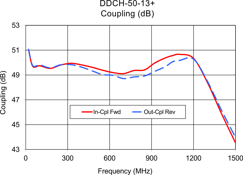
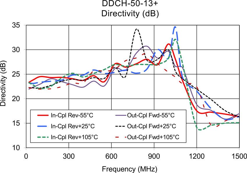
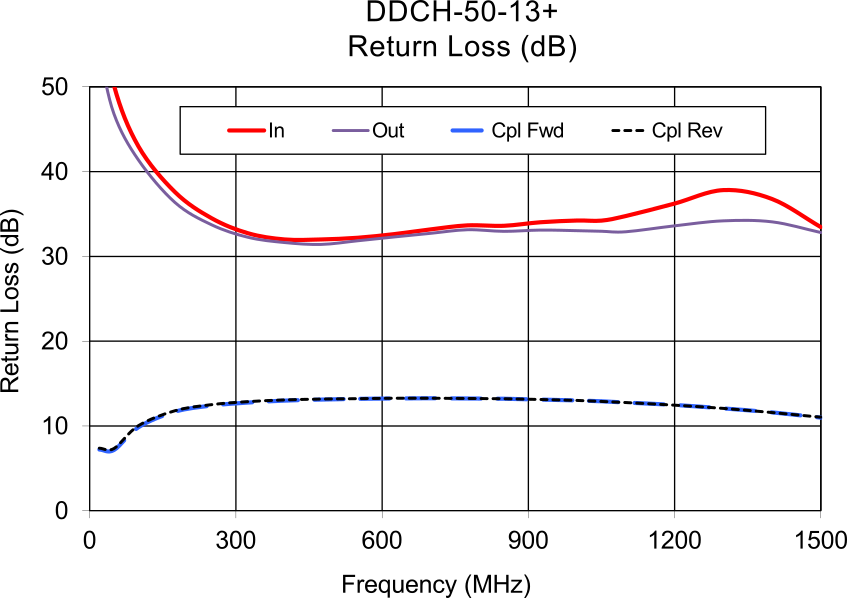
Figure 7: Performance curves for Mini-Circuits DDCH-50-13+ dual directional coupler
Directional Coupler Applications
Reflectometer
When connected as shown in Figure 8, the coupled port provides a sample of the wave reflected by the load. This allows measurement of reflected power, representing the degree of mismatch of the load. When placed at the transmitter output, this configuration can monitor the VSWR of the antenna system, both for measurement and monitoring. Many RF systems include adjustments for minimum VSWR, while others include detection of excessive VSWR for circuit protection, usually by either reducing power or shutting down.
Forward Sampling
When incident power is applied to the input port, the coupled port provides a sample of the output (forward signal) attenuated by the coupling factor. This sample can be used for waveform monitoring, spectrum analysis, and other test and measurement functions.
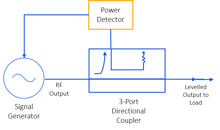
Leveled Generator
The sample may also be used to drive feedback circuitry. One important application of this type is leveling the amplitude of a signal generator, providing a constant signal source for a test system.
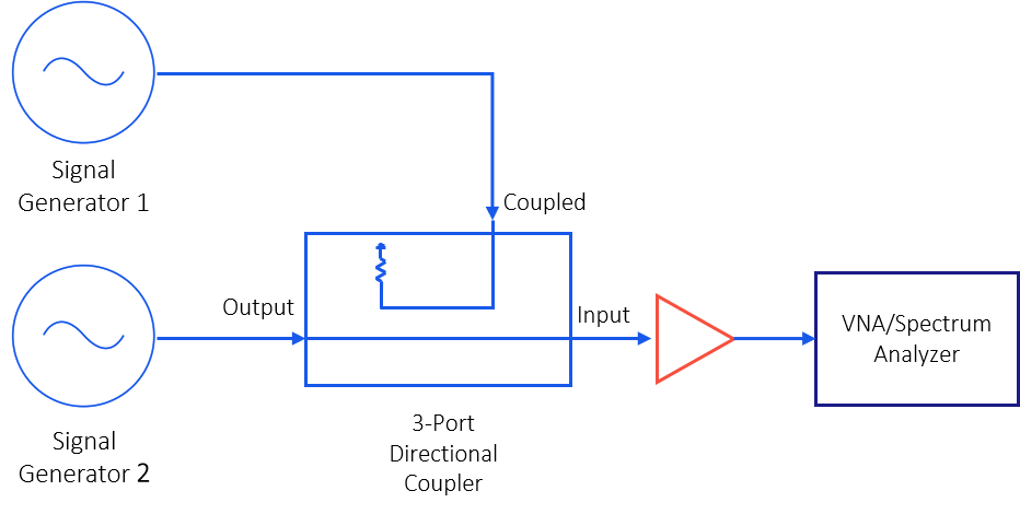
Receiver Intermodulation Test Setup
The test signals for 2-tone testing may be combined in either a directional coupler or a power combiner. Both methods will provide the necessary isolation between the signal sources.
Bi-directional Coupler Applications
Forward and Reverse Sampling
Although measurement of reflected power/VSWR is important, it may be more useful to simultaneously sample both the forward and reflected signals. This functionality can be achieved using a bi-directional coupler, which allows monitoring and measurement of output (forward) power and reflected (reverse) power. Built-in test (BIT) systems, production testing, and routine operational monitoring all benefit from bi-directional coupling.
Dual Directional Coupler Applications
Forward and Reverse Sampling
As noted above, and in Figure 6, the dual directional coupler acts as a bi-directional coupler, but with separate forward and reverse coupling paths. This provides isolation that eliminates the effects of mismatch of one path on the other path. Accuracy is thus improved, especially under conditions where one coupled port or the other may have a significant mismatched load.
Summary
Directional couplers are important devices in RF systems. Their ability to sample the forward and/or reverse direction of signal propagation allows a wide range of applications in test, measurement, monitoring, feedback, and control. This note should help system designers understand the function, architecture, and performance of the coupler so he or she may select a suitable type for their particular application.
Find the right directional, bi-directional, or dual directional coupler for your application from the hundreds in the Mini-Circuits catalog.